National WWII Glider Pilots AssociationLegacy Organization of veterans National WWII Glider Pilots Association. Discover our History, Preserve our Legacy | ||
|
A serious glider accident occurred August 1, 1943 at Lambert Field, St. Louis, MO. The sixty-fifth CG-4A, #42-78839, built by the Robertson Company, was towed aloft for publicity demonstration flights. On the first flight, six people were on board and the flight and landing were satisfactory.1 On board the second flight were Capt. Milton C. Klugh, pilot; Pfc. J. M. Davis, co-pilot and mechanic; Lt. Col. Paul H. Hazelton, AAF resident representative, St, Louis area office; William B. Robertson, president; and Harold H. Krueger, VP and production manager, both of the Robertson Aircraft Company; William Dee Becker, Mayor; Charles L. Cunningham, Deputy Controller; and Max H. Doyne, Director of Public Welfare, of the city of St. Louis; Thomas N. Dysart, president St. Louis Chamber of Commerce; and Henry L. Mueller, Judge, St. Louis County During the second flight, Capt. Klugh radioed the tug pilot at 3:55 P.M. he was going to pull up to release. At release, the right wing rotated upward and tore away from the wing root. The glider was approximately fifteen hundred feet above the ground and immediately turned nose down. All on board were killed. Investigation the next day established the wing strut end, part number 28207, broke. Part #28207 bolted to the fitting on the fuselage floor. The fitting was manufactured by machining from solid bar stock. The finished thickness of this part was to be not less than eleven thirty-seconds of an inch. The finished thickness of the broken part was less than two thirty-seconds of an inch. The fitting was manufactured by Gardner Metal Products Co., a former casket manufacturer in St. Louis. This company manufactured this part for both Robertson and Laister-Kauffmann. On receipt of these parts, each glider manufacturer inspected the parts and shipped them to Aircraft Metals Manufacturing Co. of St. Louis, Missouri that assembled the strut tubes by welding the end, part #28207, into the tube. After that, the glider manufacturer had no way to verify the end parts he had accepted or rejected were in the strut tube assemblies received from Aircraft Metals Manufacturing. Mr. Jack Laister of the Laister Kauffmann Co told me that just two months prior to this crash his company had rejected quite a number of these parts from Gardner because of walls being as thin as three thirty-seconds of an inch. Although machined so thin, this part on the crashed glider, had withstood the stress of the load caused by the pull up for release on the first flight. However, it may have begun to crack or break on that first flight. After the crash, all CG-4A gliders built by Robertson and Laister-Kauffmann were grounded until inspection of part number 28207 proved to be satisfactory.2 The Robertson inspectors responsible for these parts were relieved of their jobs and refused any job on government work within the St. Louis 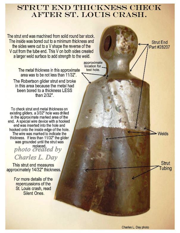
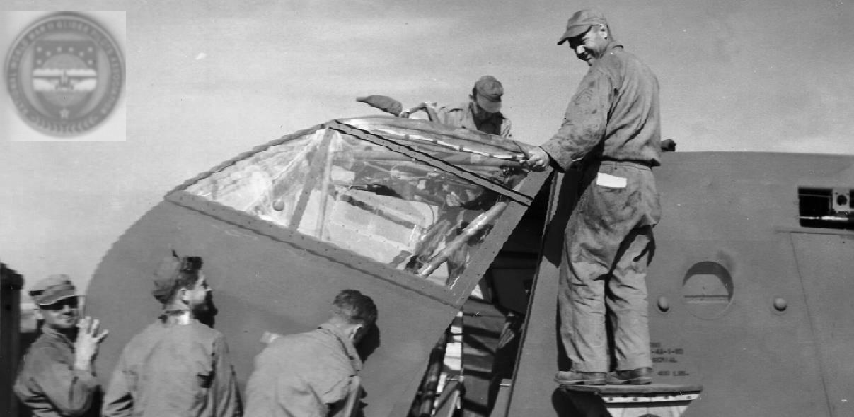
Photo of lower end of wing strut part #28100 at Silent Wings Museum, Lubbock, TX. Photo is inverted. area and refused work in any aircraft manufacturing plant in the country. The August 11, 1943 War Department, Bureau of Public Relations press release states that Mr. Charles C. Latty, the Army Air Force inspector in charge and Mr. William A. Williams, the Army Air Force receiving inspector, had been temporarily suspended. This was purportedly the only known crash of a CG-4A caused by faulty manufactured parts. However, a USAAF glider pilot who ferried gliders from the factories to glider pilot training bases told me that before the St. Louis incident, he and other glider pilots were standing under a CG-4A after flying one day. One of the men leaned against the main strut of one wing and the strut broke away from the fitting at the fuselage floor. 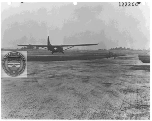
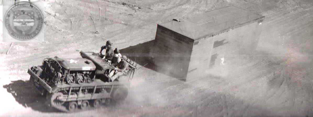
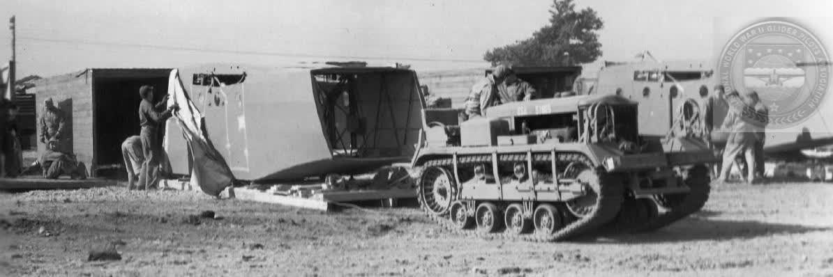
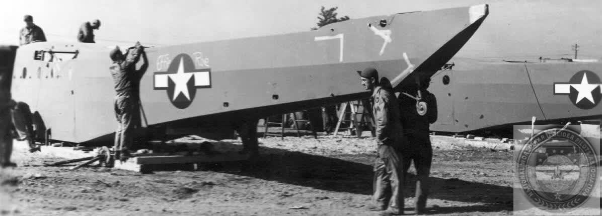
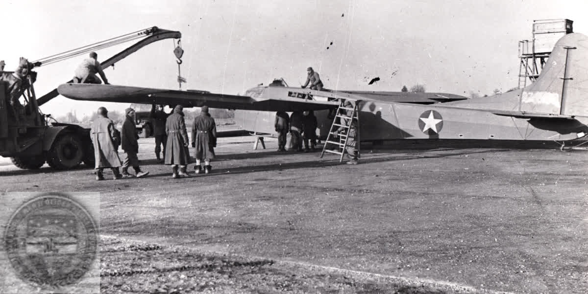
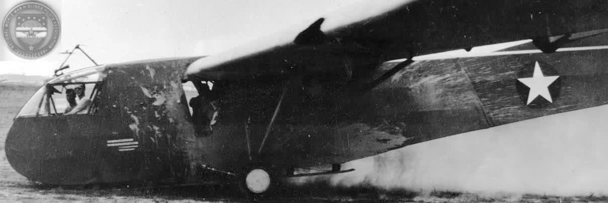
Robertson CG-4A being towed off for fatal flight. 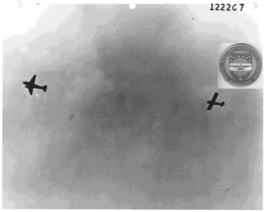
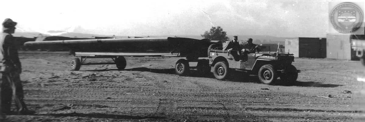
Robertson CG-4A on tow just before cut-off and fatal crash. 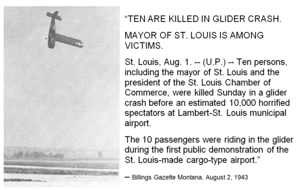
Billings Gazette Montana, August 2, 1943. This pilot also stated that there were at least two CG-4A gliders that lost a wing in flight while being ferried from a factory. Thus, one might say that it took the St. Louis crash resulting in the death of civilians to attract the attention of the Army inspectors. An unnamed officer from Clinton County Army Air Field travelled to St. Louis to inspect the glider wreckage and help determine the cause of the crash. To inspect and measure the metal thickness of the assembled gliders in question, Wright Field Glider Branch engineer, Lt. Marion "Smokey" Miller devised a wire measuring device. It was a small piece of wire with a slight hook on the end with increments marked above the hook. A small hole was drilled through the shoulder of part 28207. The wire was inserted into the hole and hooked on the inside, thus measuring the wall thickness. If the thickness was satisfactory the hole was to be closed again with a self-tapping screw or a wooden peg. If the thickness was not satisfactory, the glider was to be grounded until the wing strut assembly could be replaced. The first Technical Order #09-40CA-35 covering inspection of the wing struts was dated August 4, 1943 specified that one 3/32" hole be drilled through the strut end wall tapered surface of part #28207. On August 10, 1943 a second technical order of same number was issued. This order specified that the wings be jacked to remove weight on the strut end and the strut be unbolted and removed from the fuselage fitting. This technical order applied to 180 Robertson and Laister-Kauffmann gliders of specified serial numbers including all gliders which had been checked under the August 4 Technical Order. This order required drilling of two 1/16” diameter holes to check the metal thickness. One hole was to be drilled just inside the weld and the other on the flat surface of the cone at the base of the fillet. Any wall thickness measuring less than 11/32" was to be rejected and the glider grounded. The bolt hole also was to be measured and the strut rejected if the hole was elongated or oversize more than .001 of an inch from 7/8" (.875) diameter. In addition to the inspection of lower fitting part #28207, technical orders dated September 6 and November 26, 1943 added the inspection of fittings on the upper ends of the wing struts, part #28208 (forward tube), and part #28379 (rearward tube) welded into the upper ends of the wing strut tubes. The wall thickness of part #28379 was to be inspected through the tapped hole of the part with the wall thickness to be no less than 5/32” thickness. The wall thickness of part #28208 was to be no less than 9/32" thickness and was to be checked by drilling a 5/8” diameter hole through the end of the fitting at the center line of the fitting. The November order covered 3,803 production articles built by 12 of the 16 manufacturers with serial numbers prior to a specified serial number for each listed company. National, Cessna, Babcock and Ward gliders were not included. Any strut failing to have any of these minimum thicknesses was to be rejected and replaced with complete new wing strut part #28100 R or #28100 L. The rejected struts were to be returned to the air depot for repair. For those who incorrectly feel the CG-4A glider was a flimsy, perhaps a poorly engineered and shoddily built aircraft I close with the following paragraph of a letter mailed to me while the letter writer was reading my book (circa 2002), Silent Ones WWII Invasion Glider Test & Experiment Clinton County Army Air Field Wilmington Ohio, by Mr. Joseph R. Harris who was a WACO engineer assigned to the glider design group.
======================================== |
CG-4A WWII CARGO GLIDER GENERAL SPECIFICATION - CG-4A
Wing Span -- 83', 8" Length (Overall) -- 48', 3-3/4" Height -- 12', 7-7/16" Weight, design -- 3,750 lbs Gross Weight, design -- 7,500 lbs Wing Chord -- 10', 6" Specs for covering the CG-4A call for: Flightex Intermediate airplane fabric manufactured by Suncook Mills, or an equivalent light airplane cotton fabric. More Specifications
CG-4A WAS FLIMSY? COMMUNICATION SYSTEM CG-4A Loads CG-4A Load Facts CG-4A Cockpit CG-4A Instrument Panel  STORIES:
|
The HORSA GLIDER |
GLIDER PICKUP/Snatch Snatching a Glider RECLEMATION American Glider Pilots Captured by British A/B by William SIMONSEN Double Snatch by Charles Day First Glider Snatched from Normandy by Gerald BERRY REMAGEN Glider Retrieval by Jungle Moonlight: Burma, 1944 by Leon SPENCER Charles DAY Keith H. THOMS NWWIIGPA Deputy Wing Commander
Eastern United States Military Snatch Pickup Summary
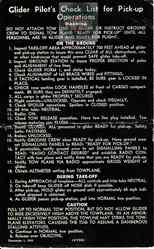
Glider Pilot Check List
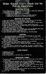
Glider Ground Crew Check List
|
OUR TOW SHIPS |