National WWII Glider Pilots AssociationLegacy Organization of veterans National WWII Glider Pilots Association. Discover our History, Preserve our Legacy | ||
|
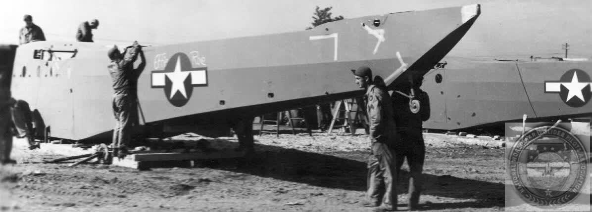
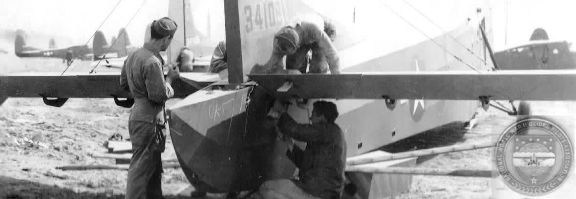
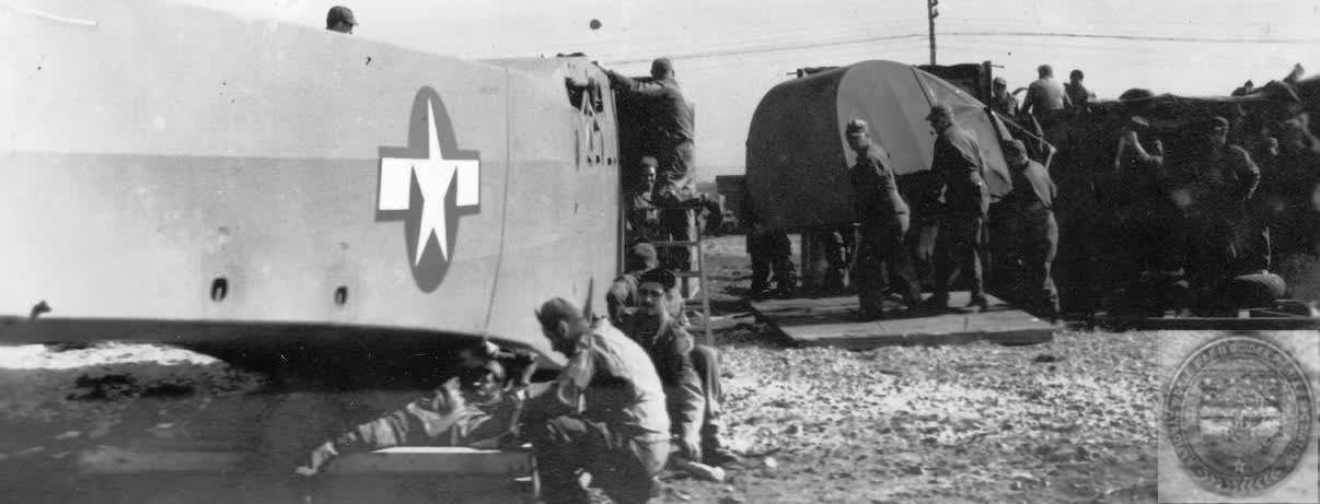
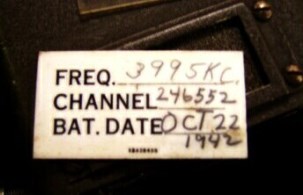
You may have read that the wire-on-the-tow-line inter-phone communication between the glider and tug were replaced by a radio system. This actually is reversed. The inter-phone wire-on-the-tow-line actually replaced the radio system. CG-4A glider specification #1326 by WACO, Troy, Ohio, was released September 19, 1941 and was replaced by #1326-A of February 4, 1942 The September 19, 1941 #1326 specifications for the CG-4A radio system installation called for two radio units. The government was to furnish both units to the glider contractor who was to install them. These are noted as GFE (Government Furnished Equipment). One unit was to weigh 15 lb. and be mounted within sight and reach of the pilots. The other unit was to weigh 25 lb. to be mounted near the rear doors. Both units were to be mounted in a way to make removal prompt and simple, to be carried out of the glider by the disembarking troops. In 1933 the Galvin Manufacturing Company (Motorola) of Chicago developed the “Walkie-Talkie” portable radio for the Army. This unit was a back-pack unit, including the battery, weighing approximately 50 pounds. In 1940 Galvin chief engineer, Donald H. Mitchell, while watching infantry manoeuvres in Wisconsin, conceived the idea of building a smaller, more portable radio that could be easily carried by an infantry soldier. This idea resulted in the “Handie-Talkie” radio which was described as being smaller than a “(soda) cracker box”. It was a transmitter and receiver unit designated BC-611. WACO report 1326-A dated 4 February 1942 revisions specified radio set SCR-585-A for communication in the CG-4A. The March 16, 1943 CG-4A Appendix D revision continued to specify radio set SCR-585-A as GFE. This radio system was composed of a receiver-transmitter BC-721 (a modified BC-611), control box BC-722, mounting base FT-295, batteries, 14 foot 7 inch MC-365 control cable, jacks, plugs, communication cordage, 43 foot antennae wire and insulators, one throat microphone and two headsets. By June 1943, mainly consisting of the Cessna deliveries, over 1,000 CG-4A gliders had been delivered. By this time, Ford had delivered approximately 400 CG-4A gliders. Ford photo #76 dated June 4, 1943 shows a Ford glider with the SCR-585-( ) radio installed. Glider deliveries were not to be delayed by shortages of equipment not critical to safe flying. Thus, if SCR-585-( ) units were not available, CG-4A gliders would be delivered without the radio system, especially during the August through December 1942 period of rush Cessna deliveries. This also applied to 1943 deliveries by the other contractors. Motorola Heritage Services and Archives correspondence of May 8, 2008 confirms that Motorola delivered 7,000 SCR-585-( ) glider version Handie-Talkie radio systems. Thus, if all Training Gliders (TG) and the CG-3A nine place cargo glider, which preceded the CG-4A, had the SCR-585-( ) radio system installed, this would leave more than 6,000 radios for installation in the almost 9,000 production CG-4A gliders built by December 1943. The radio (BC-721) of the SCR-585-( ) system was mounted in the FT-295 base unit in the corner, near the top of the glider, above the “V” shaped emergency escape door, ahead of the 3¼ inch diameter cross member in the cargo section. The control shaft and communication cordage ran from this unit overhead and down to the control box (BC-722) just below the instrument panel. Thus, as with the surface control cables, the nose could be opened without severing the radio cordage controls. The antenna wire for the radio was 43 feet long and ran between the vertical stabilizer and one leg of the nose-opening tripod. The wire was insulated at each end. A wire ran from the radio unit directly up through the fabric to this antenna wire. These radios were powered by self-contained dry cell batteries which had a life of approximately one hour if left turned on. At some point, in the neighborhood of 1,200 to 1,400 units, the BC-721-A was changed to BC-721-B. Both units were contracted by Wright Field and not by the Signal Corps in Philadelphia as were the infantry radios, BC-611. 1942 Contract #1146-WF-42 covered the SCR-585-A systems and 1942 contract #4267-WF-42 covered the SCR-585-B systems. The author has access to a BC-721-A radio, serial #251, carrying an ID card (penciled), dated Oct 22, 1942 with assigned call number 246552. A copy of the Aircraft Identification Card for CG-4A #42-46552 shows this to be the first Gibson production article delivered October 25, 1942. The AIC shows this glider arriving by air at Ardmore, OK on 4 January 1943, then to Sedalia, MO on 6 April 1943, then to Alliance, NB on 7 June 1943, then was surveyed (removed from inventory) December 1943. It likely was at this time that BC-721-A serial #251 first changed to private ownership status. These BC-721 radios could be used on several frequencies, but they were not “dial” tunable. The frequencies were tuned using crystals which required partial dismantling of the radio, removing one crystal and inserting another. If a radio was left on continuously by forgetfulness or deliberateness, the dry cell batteries could last only slightly more than an hour. On the ground these radios had a range of a mile or less. In the air, the broadcast/receive distance was approximately three miles and anyone with a “dial” tunable radio could tune to the fixed frequency of the BC-721. Mr. Ray Connigham of the Assault Glider Project (UK) stated to me that the British, very early (1941), experimented by running two separate communication wires through the center of their hemp tow lines. The parting point of hemp line was at approximately 10% elongation or stretch. A Horsa glider under tow did not generally cause 10% elongation of its hemp tow line, yet under tow, the wires woven into the line broke. The wire-on-the-tow-line inter-phone does not appear in glider training manuals until late 1943 and early 1944. Late 1943 glider photographs at the glider experiment base at Clinton County, Ohio (CCAAF) show the new, field installed, bolt-on Griswold nose protection device (these were not factory installed until 1945 contracts) show a plug receptacle near the tow release for connecting the inter-phone tow-line cable. The insulated, three-wire inter-phone cable between the glider and tug, was tied to the 350 foot long, 11/16” diameter nylon tow line with small diameter nylon cord in 16” “loops” every 12” of tow line, making the cable 25% longer than the tow line “at rest”. This was necessary because the tow line, under load, stretched more than could the wire. This 16” by 12” dimension is from glider mechanic classroom notes by F/O William Cater. Clyde Unger who rebuilt the CG-4A at Iron Mountain, MI states that Ford Motor drawings state 17” of cable per 12” of tow line. At 25% the tow line elongation calculates to 87 ½ feet. Despite this allowance for 25% stretch of the tow line, many glider pilots reported their interphone systems stopped working just after take-off. This problem could have been a single point where one wire broke, or it could have been the connection at the “plugs”. The wire-on-the-tow-line was not one continuous wire running from cockpit to cockpit via the tow line. At the glider and the tail of the C-47 tug, there were male/female connectors to plug the tow line wire into the aircraft. These were on the outside of the aircraft, out of reach from within. A connector may have loosened or one of the wires could have broken during the stress of take-off. You will read that the communication wire was incorporated into the nylon tow line by running it through the center of the line. Per historian and glider pilot Leon Spencer, this “wire-in-the-line” tow line was first contracted for in May 1945. The contract was for 37,000 lines, to be delivered 4,000 per month. This quantity is inordinately high in that fewer than 14,500 CG gliders using the 11/16” diameter nylon line had been built since 1942 and at least one-third had been lost or destroyed during training and combat missions. Despite the absolute physical impossibility of braided copper wire stretching up to 25% of its length as could the nylon line, test reports claim the wire-in-the-tow-line tests were successful. The Silent Wings Museum, Lubbock, Texas and the National Museum of the U.S. Air Force, Dayton, Ohio each display this wire-in-the-tow line. These “wire-in-the-line” nylon lines show age, but appear to be “new”, never used. There are quite a few glider cockpit photographs showing these SCR-585 systems in the glider. These vary from early WACO and Ford production photos to USAAF photos made at Wright Field/CCAAF or during training or maneuvers in the U.S. and Europe. Were these radios used in gliders flying into combat? Motorola archives say there were 7,000 SCR-585 (BC-721) radio systems built for the Army under 1942 contracts. This would mean there was a radio for just under half (approximately 46%) of all gliders (TG or CG) delivered. Radio silence was critical flying into combat and it is unlikely they were used in combat, but possibly they were in some of the gliders used in Sicily, Normandy, Southern France and Market. Also since there were quite a number of 1942 and 1943 (contract year) gliders flown in the Varsity mission, they may have had radios in them. Glider pilot opinion varies when quizzed about the radios. Some remember them, some do not. Some say they never saw or flew a glider with any type of communication system between the glider and tug. Combat related photographs of the interphone system, wire-on-the-tow-line, do not seem to appear until preparations for the September 1944 Market operation, followed by March 1945 photos of Varsity preparations. How else did the tug and glider communicate? Some methods were visual signals using colored lights flashed from the C-47 navigator's astral dome to indicate arrival at the LZ, C-47 moving wheels up and down or C-47 wing "wiggle" to indicate time to cut-off. For the glider pickup system fabric panels on the ground signaled the C-47 snatch plane. For take-off, ground crewmen hand signaled the glider and tug pilots. But when it came to voice communications between the tug and glider, the “low tech” wired systems replaced the, then, “high tech” radio. First written 05 July 2014. Copyright Charles L. Day, 2025 |
CG-4A WWII CARGO GLIDER GENERAL SPECIFICATION - CG-4A
Wing Span -- 83', 8" Length (Overall) -- 48', 3-3/4" Height -- 12', 7-7/16" Weight, design -- 3,750 lbs Gross Weight, design -- 7,500 lbs Wing Chord -- 10', 6" Specs for covering the CG-4A call for: Flightex Intermediate airplane fabric manufactured by Suncook Mills, or an equivalent light airplane cotton fabric. More Specifications
CG-4A WAS FLIMSY? COMMUNICATION SYSTEM CG-4A Loads CG-4A Load Facts CG-4A Cockpit CG-4A Instrument Panel  STORIES:
|
The HORSA GLIDER |
GLIDER PICKUP/Snatch Snatching a Glider RECLEMATION American Glider Pilots Captured by British A/B by William SIMONSEN Double Snatch by Charles Day First Glider Snatched from Normandy by Gerald BERRY REMAGEN Glider Retrieval by Jungle Moonlight: Burma, 1944 by Leon SPENCER Charles DAY Keith H. THOMS NWWIIGPA Deputy Wing Commander
Eastern United States Military Snatch Pickup Summary
Glider Pilot Check List
Glider Ground Crew Check List
|
OUR TOW SHIPS |
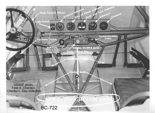
Identifying controls and items in the CG-4A cockpit. This photo was used in the original glider pilot manual of 1942. It shows the radio control box BC-722 and the push/pull, talk/listen knob
Courtesy USAAF / Charles Day and John Harris Collection
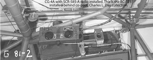
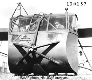
USAAF photo G 81-2 from CCAAF glider test field. Photo shows the BC-721 radio mounted in FT-295 mounting.
Courtesy USAAF / Charles Day Collection
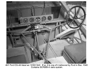
Ford Motor Company CG-4A cockpit photo #41 of December 20, 1942 showing single steering glider with BC-722 control box and push/pull knob, one of four Ford built CG-4A delivered in December 1942
-300x174.jpg)
Charles Day Collection
Side of BC-721 A radio showing antenna connection port, talk listen rocker switch and the Frequency, Channel, and Battery Date card and card holder on the radio.
Charles Day Collection
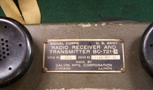
I.D. plate for BC-721 A radio show above
Charles Day Collection
Closeup photo of Frequency, Channel, Battery Date card for BC-721 A radio.
Charles Day Collection
scan image of Aircraft Identification Card of Gibson Refrigerator CG-4A #42-46552.
Courtesy USAAF / Charles Day Collection
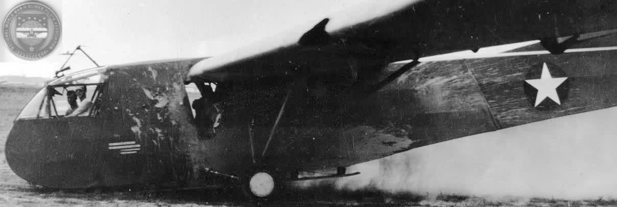
USAAF Wright Field photo #130157 at CCAAF, new Bolt-on Griswold nose protection device showing receptacle for wire-on-tow-line interphone wire connection.
_Lrg-304x339.jpg)
Courtesy F/O William L. Cater / Charles Day Collection
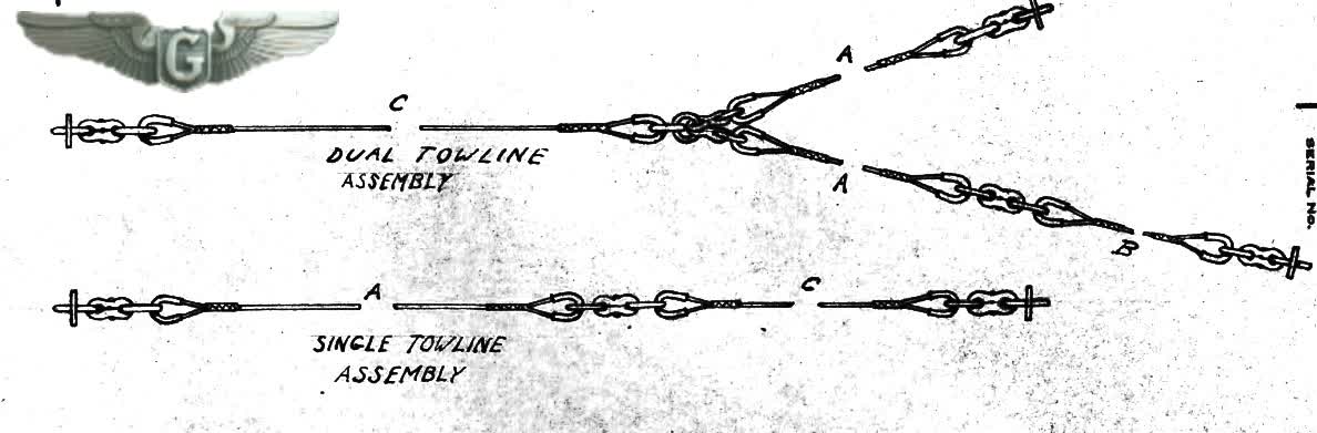
Depiction from drawings and classroom notes of F/O William L. Cater showing the instructions for length of cords and spacing for tying interphone wire to tow line.
Courtesy National Archives / Charles Day Collection
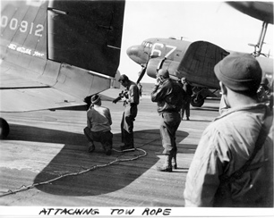
Signal Corps photo of men attaching wire-on-tow-line to C-47 for Market mission or the Varsity mission.
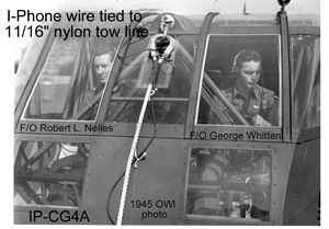
Courtesy OWI / Charles Day Collection
Charles Day Collection
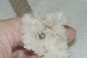
Photo shows the red, black and white wrapped braided wire protruding from ends of the three strands of nylon tow line from May 1945 contracts.
Charles Day Collection
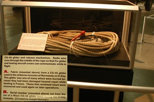
A complete wire-in-the-tow-line is displayed at the National Museum of the United States Air Force, Dayton, Ohio.